Chapter 14
DISTILLATION EQUIPMENT
Distillation equipment can be divided into several categories. Simple apparatus, such as illustrated in Figure 11-1, can be constructed on a large scale. However, such a simple "pot still" would achieve less than 100 proof on the first run from an average beer and many separate distillations would be necessary to achieve 190 proof or 95% alcohol. For the production of fuel alcohol such a unit is not economical either in terms of energy input or labor. The only exception would be if the alcohol were used in an injection system where low proof is acceptable.
Rectifying columns, on the other hand, can achieve 190 proof on the first run. Stills incorporating rectifying columns can be designed to run either on a batch or continuous basis. A batch operation still is simply a reflux rectifying column attached to a suitable boiler. The boiler is loaded with beer, the alcohol is distilled out of the beer, and then the still is shut down while the stillage is emptied from the boiler and a fresh batch of beer run in. Continuous operation stills, on the other hand, do not have to be shut down periodically. They can be operated 24 hours a day and, with proper automatic controls, require very little attention.
Figure 14-1: CROSS SECTION of LARGE COLUMN
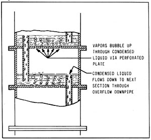
The basic packed reflux column described in Chapter 11 is only efficient up to a certain point. Figure 14-1 illustrates a cross section of a larger apparatus that operates on the same principle. Here, ascending vapors rise through holes in a perforated plate. The descending liquid flows downward from plate to plate through down-pipes. The liquid does not flow through the holes in the plate because of the pressure exerted by the ascending vapor. Thus, a certain amount of liquid is "trapped" on each plate and, as the vapors bubble through it, alcohol is removed from the descending liquid. The effect is similar to the packed reflux column in that a separate "distillation" is performed at each plate. The plate design shown is only one of several possibilities. Various forms of bubble caps, for example, are used on larger columns.
Figure 14-2: CONTINUOUS STILL
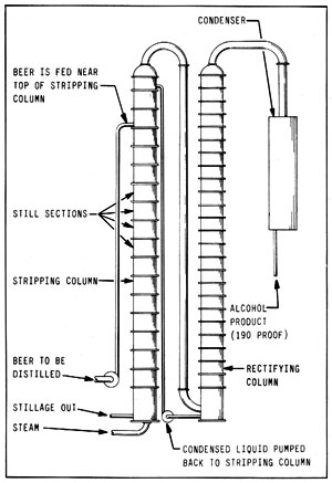
Figure 14-2 is a continuous distillation apparatus incorporating the plates described in Figure 14-1. The apparatus illustrated consists of two columns, although there is no reason why the unit could not be constructed as a single column. The liquid to be distilled (beer) is pumped into the first column near the top. Steam is piped in at the bottom. As the beer descends, the steam "strips" it of alcohol. The alcohol vapors pass over to the next column, and the alcohol-free liquid (stillage) exits from the base. The next column also contains plates similar to those in the first. In this column the alcohol vapors are stripped of most of the remaining water (or "rectified") and exit as 190 proof (95%) alcohol.
The distillation equipment described so far uses the principle of adding heat to boil the beer and provide vapor for the distillation process. Alternately, vapor can also be produced by reducing pressure. In a vacuum, it is easily possible to boil ice water at 32 deg F. Similarly, alcohol/water mixtures can also be boiled at "room" temperature and below simply by reducing pressure. The equipment consists of a vacuum pump, condenser, and a still pot built to withstand the external pressure created by the vacuum. Although the energy required to run the vacuum pump is probably equal to the amount of energy required to operate a conventional still, this type of equipment merits consideration.
The selection of distillation equipment is largely a matter of economics. Continuous operation stills must be properly engineered and are costly to construct. However, the advantages of automated operation and low labor requirements make them very attractive. For operations producing a large amount of fuel, a continuous still clearly makes sense. Batch stills, although labor intensive, can be built by the layman with relative ease and for a small amount of money. The balance of this chapter describes the construction and operation of such equipment.
Note that solar energy can be used in several ways to provide heat for the distillation process. Solar stills are discussed in Chapter 15.
SIMPLE REFLUX COLUMN
Figure 14-3 shows a simple rectifying reflux column. The column is simply a length of pipe filled with a packing material to provide a large internal surface area. Aside from the pipe to hold the packing, some sort of screen or retainer is needed at the base of the column to keep the packing from falling into the boiler. The thermometer at the top of the column is necessary to check the temperature of vapors going to the condenser.
Figure 14-3: SIMPLE REFLUX COLUMN

A 3-inch diameter column of this design should be about 4 feet long. It would be capable of producing about 1 gallon per hour, depending on the initial concentration of the beer. Similarly, a 4-inch column should be about 6 feet long and should deliver about 2 gallons per hour; a 6 inch column should be at least 10 feet in length and should be capable of 5-6 gallons per hour. Columns of this design do not work well in diameters above 6 inches.
CONDENSERS
The top of the column will have to be connected to a condenser to cool the vapors back into the liquid form. The condenser can be a coil of soft copper pipe inside a suitable container as illustrated in Figure 14-4. Here water is used as the heat exchange medium. On small stills, air cooled condensers are also possible. An old automobile radiator should work very well. The main thing is that the condenser be large enough to cool all of the vapors from the still below 100 deg F. and, preferably, to about 60 deg F.
Figure 14-4: CONDENSER CONSTRUCTION
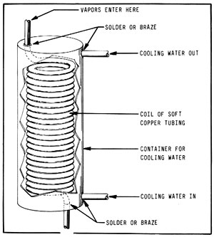
Also, if the vapors going into the condenser are impeded in any great degree, pressure could build up inside the column and boiler. Therefore, the diameter of tubing in a condenser for a 3-inch column should be no smaller than 3/8 inch diameter. For a 4-inch column, 1/2 inch tubing would be the absolute minimum, and for a 6-inch column, the minimum would be 3/4 inch diameter. Note that the effective diameter of a condenser can be increased by connecting two or more condensing coils in parallel.
BOILERS
To complete the basic apparatus, you will need a boiler or "still pot". A 55-gallon drum can be adapted to this purpose. The drum is best placed on its side to allow maximum surface area for heating and the production of vapor. Alternately, a small column could be attached to the cooking and mashing drum illustrated in Figure 13-1. A more efficient boiler could be made from a hot water heater. Hot water heaters are available that can be fired with wood, coal, electricity, or gas. They are usually glass lined and insulated. Serviceable units can often be found in a junk yard and rebuilt. Other types of boilers can also be adapted for use as a still pot. An example might be certain types of home or commercial hot water furnaces.
REFLUX CONTROL
Successful operation of the simple reflux column described earlier depends on careful regulation of the amount of vapor going to the column. However, it is often difficult to control the amount of vapor produced by boilers that are fueled by wood, coal and similar materials. The reflux control coil illustrated in Figure 14-5 can be added to the column and used to regulate temperatures at the still head with a great degree of accuracy. The reflux control unit is simply a condensing coil placed in the column and used to control the amount of reflux. It is constructed by wrapping soft copper tubing around a suitable form. The copper coil is then placed inside a section of the column.
Figure 14-5: REFLUX CONTROL COIL
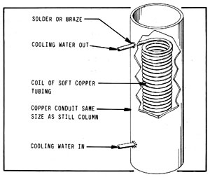
In use, cooling water is circulated through the coil to condense a portion of the ascending vapors and, thus, increase the amount of reflux. Adjustment of cooling water in the reflux coils must be very precise. Small needle valves designed for precision metering of liquid should be used. Semi-automatic operation of the still could be achieved by replacing the cooling control needle valves with solenoid valves controlled by temperature sensors within the column.
HYDROMETER SUMP
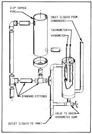
There are several improvements that can be added to the basic still. One of them is a hydrometer sump as illustrated in Figure 14-6. It is constructed of ordinary pipe and fittings. In use, the product from the condenser is admitted at the bottom and flows out of the top. The hydrometer and thermometer allow a constant check of the proof of the alcohol being produced by the still. The valve at the bottom of the sump allows the unit to be drained.
Figure 14-6: HYDROMETER SUMP
CONSTRUCTION OF A REFLUX COLUMN
Figure 14-7 illustrates a reflux column incorporating two reflux control coils, a hydrometer sump, and related plumbing. The layout of the condenser, pipes, valves, etc. is for clarity in the illustration and not necessarily the best configuration.
Figure 14-7: IMPROVED REFLUX COLUMN
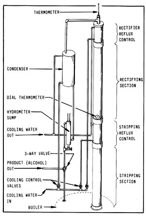
The column can be constructed from copper, iron, or steel pipe and fittings. Aluminum is not suitable because it can react chemically with the alcohol. The use of certain types of rubber and plastic that are attacked by the alcohol should also be avoided. Copper pipe and fittings, although expensive, are easy to work with and are recommended.
To construct, for example, a 4-inch column, begin by cutting a 6 foot length of pipe for the rectifying section, a 2-3 foot length for the stripping section, and two lengths about 1 foot long for the reflux control sections. Note that the use of two reflux control sections allows very precise control of temperatures within the column. However, if an easily controlled heat source, such as gas or electricity, is used for the boiler, the lower coil can be eliminated. The reflux control coils are soft copper tubing, 3/16 to 3/8 inches in diameter wound around a suitable form and placed inside the short sections of pipe.
Both the rectifying and stripping sections should be packed. The packing can be marbles, pebbles, broken glass, short pieces of metal or glass tubing, or whatever. Anything that won't rust or react with the alcohol will work. However, the best packing for this type column is probably copper or stainless steel scouring pads. Ordinary steel wool will not work because it will quickly rust. Some sort of screen or retainer is needed at the base of each packed section to keep the packing material from falling into the boiler. The simplest retainer is a section of coarse screening cut to the column diameter and soldered into place.
Once packed, the entire unit can be assembled. The drawing shows the sections joined by pipe couplers.
Figure 14-3 shows the thermometer (or other temperature sensing device) being held in place by a cork. This is intended as a safety device. Excessive pressure will pop the cork. If some other arrangement is used to hold the temperature sensor, a pressure relief valve, such as used on hot water heaters, should be added either in the column or the boiler.
A worthwhile improvement would be the use of remote sensing thermometers (thermocouples or thermistors) with the read-out located in some convenient place, for example, near the reflux control needle valves. As mentioned earlier, the use of solenoid valves, controlled by remote temperature sensors, in place of (or preferably in conjunction with) the reflux control needle valves would allow semi-automatic operation. A thermometer to measure vapor temperature in the boiler (not shown) is also necessary.
The three-way valve located below the hydrometer sump allows the impure product to be run back into the boiler for redistillation. In addition, two collection tanks, one for high proof product and one for low proof residue, are needed. As will be explained in the section on still operation, the low proof tank should be set up so that its contents can be run back into the still pot at the beginning of each successive run.
OPERATION OF THE STILL
In operation, the boiler or still pot is filled to no more than the 3/4 level with the beer to be distilled. As the liquid begins to boil, vapors rise in the column. After a while, the column will come up to temperature, and an equilibrium will be established. For a normal beer concentration of about 8%, the initial temperature of the vapors in the still pot will be about 200 deg F. The vapors will cool as they rise in the column and, at the top, they should stabilize at 173 deg F which is the approximate boiling point of the water/alcohol azeotrope.
If the boiler is supplying more vapor than the column can handle, the temperature at the still head will rise above 173 deg F and the proof of the product going to the condenser will be reduced. Conversely, if the boiler is not producing enough vapor, the temperature at the still head will be low and no vapors will be going to the condenser. On a still without reflux control coils, the heat source at the boiler must be adjusted to keep the amount of vapor within the range that can be handled by the column. On stills with reflux control1, the boiler is adjusted to produce an excess amount of vapor. The lower reflux control coil is adjusted so that the thermometer located just above it reads 180 deg F and the top reflux control coil is adjusted to maintain the still head temperature at exactly 173 deg F.
After the column has stabilized, the 3-way valve is opened to let the product flow to the high proof tank. Note that when you begin a distillation run, certain low boiling vapors may come over, and a small amount of liquid may come out of the condenser that is not ethanol. This liquid is composed of substances in the beer that have a lower boiling point than ethanol. However, they do not affect fuel value and, for all practical purposes, can be ignored.
As the distillation progresses, the vapors in the still pot will contain a greater and greater percentage of water and a correspondingly lesser proportion of alcohol. The still pot vapor temperature will rise. Eventually, a point will reached where there is too little alcohol in the vapor for the column to achieve effective separation. The temperature at the still head will rise slightly and the proof of the product will be lower. At this point, it is best to collect the product coming from the condenser in the low proof container mentioned earlier.
The distillation should be continued until the temperature at the still head equals the temperature of the vapors in the boiler, which will be near 208-212 deg F depending on altitude, atmospheric pressure, and the amount of dissolved material in the beer. Note that when switching to the low proof phase of the distillation, the reflux control coils should be turned off and the column temperatures allowed to rise naturally.
When all the alcohol has been removed from the beer, as indicated by boiler and still head vapor temperatures, as mentioned before, the distillation is complete. The beer, now called "stillage", is drained from the boiler, and a fresh charge of beer run in. The low proof "tail" from the previous run is added to the fresh charge of beer, and the still is ready for another run.
CAUTION
There are several inherent dangers in the construction and use of the equipment described in this chapter. Alcohol, and alcohol vapors, are flammable. Mixtures of alcohol vapors and air can be explosive. The equipment should be located in an area that receives adequate ventilation, and preferably outdoors or in a simple shed away from other buildings. The still should be electrically grounded to prevent the buildup of static electricity. Above all, reasonable care and common sense should be exercised. If you are not sure about something that could be potentially dangerous, find out before you proceed!
Chapter Index
Chapter 1 AN OVERVIEW
Chapter 2 BASIC FUEL THEORY
Chapter 3 UTILIZATION OF ALCOHOL FUELS
Chapter 4 ETHANOL PRODUCTION - GENERAL DISCUSSION
Chapter 5 PROCESSING STEPS COMMON TO ALL MATERIALS
Chapter 6 PROCESSING STEPS SPECIFIC TO SACCHARINE MATERIALS
Chapter 7 PROCESSING STEPS SPECIFIC TO STARCHY MATERIALS
Chapter 8 PROCESSING STEPS SPECIFIC TO CELLULOSE MATERIALS
Chapter 9 YEAST AND FERMENTATION
Chapter 10 INDIVIDUAL RAW MATERIALS
Chapter 11 DISTILLATION
Chapter 12 DRYING THE ALCOHOL
Chapter 13 MASHING AND FERMENTATION EQUIPMENT
Chapter 14 DISTILLATION EQUIPMENT
Chapter 15 SOLAR STILLS
Chapter 17 PUTTING IT ALL TOGETHER
Chapter 18 THE FUTURE
Biofuels
Biofuels Library
Biofuels supplies and suppliers
Biodiesel
Make your own biodiesel
Mike Pelly's recipe
Two-stage biodiesel process
FOOLPROOF biodiesel process
Biodiesel processors
Biodiesel in Hong Kong
Nitrogen Oxide emissions
Glycerine
Biodiesel resources on the Web
Do diesels have a future?
Vegetable oil yields and characteristics
Washing
Biodiesel and your vehicle
Food or fuel?
Straight vegetable oil as diesel fuel
Ethanol
Ethanol resources on the Web
Is ethanol energy-efficient?