Chapter 13
MASHING AND FERMENTATION EQUIPMENT
GENERAL DISCUSSION
Milling, extracting, cooking, conversion, and fermentation equipment can be designed to operate on either a batch or continuous basis. Batch equipment can be built in almost any size. However, it does not lend itself to complete automation and, thus, is more labor intensive. Continuous equipment can be fully automated, but it is expensive to engineer and construct.
An example of continuous cooking is a "jet" cooker. The mash slurry is injected into a pipe along with steam at about 150 pounds pressure. It is quickly cooked (usually in a matter of minutes) and emerges from the other end of the pipe ready for cooling and conversion. If the mash slurry is acidified (as described in Chapter 7), cooking and conversion take place simultaneously, and the mash emerges from the cooker ready for fermentation.
Slightly less complicated is the use of high pressure steam for batch cooking. Here a pressure vessel is used instead of the jet cooker. Although the operation is not continuous, cooking times are very short and simultaneous cooking and conversion are possible with the acid hydrolysis process.
Fermenters can also be run on a continuous basis. They are simply connected in series so that the mash flows from one container to the next. Continuous fermentation is best suited to continuous cooking and conversion systems where all the variables are controlled. It is very important that the feed going into a continuous fermentation system be absolutely sterile, otherwise the whole system can quickly become contaminated. Cooking with high pressure steam achieves the necessary degree of sterilization, most other processes do not.
Continuous systems, in general, are best suited to processing homogenous feedstocks of consistent quality. Batch operation is more advantageous when there are variables in feedstock quality that require adjustment of cooking, conversion and fermentation processes. Continuous equipment is also extremely expensive, whereas batch systems are less complicated and easier to construct. The following pages discuss the construction of batch equipment of different sizes and degrees of sophistication.
Figure 13-1: SMALL APPARATUS
Figure 13-2: APPARATUS ADAPTED for COOKING
BATCH COOKING AND MASHING EQUIPMENT
Cooking and mashing equipment can be as simple or as elaborate as you wish. Figure 13-1 shows a 55-gallon drum with a large gate valve installed at the bottom. Figure 13-2 shows the same 55-gallon drum mounted over a simple firebox. This size apparatus is capable of processing about a bushel (56 pounds) of grain on each run. After cooking and conversion, the gasket-sealed top and fermentation trap would allow the same container to be used for fermentation. After fermentation is complete, the addition of a simple reflux column as described in Chapter 14 would allow the same drum to be used for distillation. Used in this manner, a single 55-gallon apparatus would produce about 3 gallons of alcohol every 3 or 4 days. By adding 2 or 3 separate fermenters of 50-gallon capacity and cooking and distilling one batch per day, alcohol production could be increased.
Figure 13-3 shows a large apparatus with certain improvements. Here a 3-4 inch centrifugal pump is used to stir the mash. Note that when using a pump for stirring, the larger the diameter of the pump, the less chance of clogging. However, even with large diameter pumps, full dilution at the cooking stage is sometimes necessary to insure adequate agitation. A 3000 gallon apparatus could prepare up to 200 gallons of alcohol every 3-4 days. The addition of separate fermenters would allow production of the same amount each day.
Tanks can also be rigged with paddle-type stirrers either vertically or horizontally. Also, a "jet" mixer, which looks a little like an outboard motor, is easily clamped to the side of an open tank.
Figure 13-3: LARGE APPARATUS
Aside from the simple "tank over a fire" apparatus shown here, mash can be cooked by any other convenient source of heat. Perhaps the best would be the use of direct steam. This method requires only the absolute minimum initial dilution, or no dilution at all. Steam is simply piped into the bottom of the cooker and gelatinizes the mash. This method is particularly advantageous with potatoes where the 80% moisture content makes dilution undesirable.
One final note is that whatever source of energy you use for cooking, the apparatus should be insulated as much as possible. The better insulated the cooker, the less heat will be radiated away and wasted.
FERMENTATION EQUIPMENT
A fermenter can be made from just about any suitable tank. On a small scale, heavy duty 44-gallon plastic trash cans with sealable lids and fitted with a fermentation lock work very well. On a larger scale, plastic storage tanks, available up to 6000 gallon capacity are also excellent. The plastic has the advantage of being rust-free and easily cleaned. However, if kept clean, ordinary steel tanks or drums should pose no problem.
Figure 13-4: COOLING COIL
The other requirements for a fermenter are some sort of agitation and a means of cooling. Agitation keeps fresh nutrients available to the yeast cells. Agitation can be achieved with either pumps or mechanical stirrers as described in the previous section. Cooling is necessary, especially in large fermenters, to keep temperatures within the prescribed limits. Figure 13-4 shows an easily constructed cooling coil. The unit shown is a coil of soft copper pipe on a suitable support frame that can be moved, for example, from fermenter to mash cooker, etc. Alternately, an ordinary garden hose can be coiled inside the fermenter to achieve much the same result.
Figure 13-5: FERMENTATION LOCK
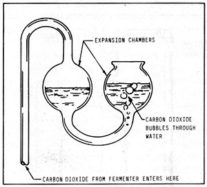
Carbon dioxide gas will be given off during the fermentation. If it is allowed to escape unimpeded, it can carry off a large amount of alcohol vapor. Figure 13-5 shows a fermentation lock available from wine making supply houses. The escaping CO2 is bubbled through water. The water traps any escaping alcohol vapors. Expansion bulbs keep the water in the trap from either being blown out or sucked back into the fermenter.
Figure 13-6: LARGE FERMENTATION LOCK
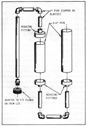
Extremely large amounts of gas are given off by large fermenters. The device illustrated in Figure 13-5 should not be used on apparatus larger than about a 5 gallon capacity. Figure 13-6 shows a fermentation lock constructed from metal or plastic pipe fittings. Such a unit constructed from 3/4 inch pipe would be adequate for a 50 gallon fermenter. Two inch pipe should be used on a 500 gallon unit, and 3-4 inch pipe on a 1000 gallon fermenter. Remember that pressure can build quickly within the apparatus and, if not allowed to escape, could cause an explosion. Therefore, a safety valve, in addition to the fermentation lock, would be a wise investment.
Continuous fermenters are simply a number of separate fermentation tanks in series. The mash should enter at the bottom of the first fermenter, exit the top, enter the bottom of the second, and so on. Total fermentation time is determined by dividing the total capacity of the fermenters by the flow rate. For example, 1000 gallon fermenter capacity and a 20 gallon per hour flow rate would give a total fermentation time of 50 hours. As noted earlier, sterile feedstock is necessary.
Chapter Index
Chapter 1 AN OVERVIEW
Chapter 2 BASIC FUEL THEORY
Chapter 3 UTILIZATION OF ALCOHOL FUELS
Chapter 4 ETHANOL PRODUCTION - GENERAL DISCUSSION
Chapter 5 PROCESSING STEPS COMMON TO ALL MATERIALS
Chapter 6 PROCESSING STEPS SPECIFIC TO SACCHARINE MATERIALS
Chapter 7 PROCESSING STEPS SPECIFIC TO STARCHY MATERIALS
Chapter 8 PROCESSING STEPS SPECIFIC TO CELLULOSE MATERIALS
Chapter 9 YEAST AND FERMENTATION
Chapter 10 INDIVIDUAL RAW MATERIALS
Chapter 11 DISTILLATION
Chapter 12 DRYING THE ALCOHOL
Chapter 13 MASHING AND FERMENTATION EQUIPMENT
Chapter 14 DISTILLATION EQUIPMENT
Chapter 15 SOLAR STILLS
Chapter 17 PUTTING IT ALL TOGETHER
Chapter 18 THE FUTURE
Biofuels
Biofuels Library
Biofuels supplies and suppliers
Biodiesel
Make your own biodiesel
Mike Pelly's recipe
Two-stage biodiesel process
FOOLPROOF biodiesel process
Biodiesel processors
Biodiesel in Hong Kong
Nitrogen Oxide emissions
Glycerine
Biodiesel resources on the Web
Do diesels have a future?
Vegetable oil yields and characteristics
Washing
Biodiesel and your vehicle
Food or fuel?
Straight vegetable oil as diesel fuel
Ethanol
Ethanol resources on the Web
Is ethanol energy-efficient?