 Roger Sanders' Waste Oil HeaterRoger Sanders' Waste Oil Heater
Free heating!
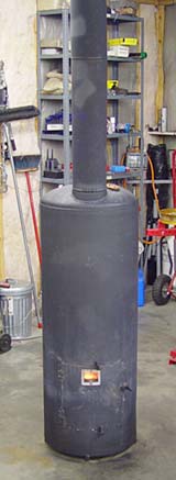
This waste oil heater will save you thousands of dollars in heating bills.
 Roger Sanders' improved version of the Mother Earth News waste oil heater solves all the problems that made the original MEN version difficult to use.
Now, after five years of use, much experimentation, many upgrades, and hundreds of letters from readers and builders, Roger has updated his original waste oil heater project with a great deal of new information and new options.
This Second Edition has far more detail and information based on practical experience. Fully illustrated with many photographs and design drawings, there are whole new sections on:
– and more. MOTHER's Waste Oil Heater -- original version Modifications: Roger Sanders' Waste Oil Heater Bruce Woodford's forced-air waste oil heater Biofuels
The Second Edition is now available as a pdf e-book for downloading:
CLICK HERE
To
Journey to Forever's forced-air biofuel heater
En español -- Biocombustibles, biodiesel
Biofuels Library
Biofuels supplies and suppliers
Biodiesel
Make your own biodiesel
Mike Pelly's recipe
Two-stage biodiesel process
FOOLPROOF biodiesel process
Biodiesel processors
Biodiesel in Hong Kong
Nitrogen Oxide emissions
Glycerine
Biodiesel resources on the Web
Do diesels have a future?
Vegetable oil yields and characteristics
Washing
Biodiesel and your vehicle
Food or fuel?
Straight vegetable oil as diesel fuel
Ethanol
Ethanol resources on the Web
Is ethanol energy-efficient?

Community development | Rural development
City farms | Organic gardening | Composting | Small farms | Biofuel | Solar box cookers
Trees, soil and water | Seeds of the world | Appropriate technology | Project vehicles
Home | What people are saying about us | About Handmade Projects
Projects | Internet | Schools projects | Sitemap | Site Search | Donations | Contact us
Our rhce and act online prep exam provide you 100% pass guarantee. You can get access to 70-642 and 000-089 with multiple prep resources of 642-467.