Farm-scale ethanol fuel production plant
Design Report
The Gildred/Butterfield Fuel Alcohol PlantGildred/Butterfield Limited Partnership
Acknowledgements
The Ethanol Fuel Plant Design Competition was managed by the Long Range Planning Unit of the California Department of Food and Agriculture as part of the Department's Ethanol Fuels Program. This report was prepared under the direction of Vashek Cervinka, program manager, Steve Shaffer, program coordinator, and Neil Koehler, project manager of the Design Competition.
The report was authored by Floyd Butterfield, the designer and operator of the selected ethanol fuel plant design and edited by the staff of the Long Range Planning Unit. The blueprints were prepared by Buchanan's Drafting Service in Paso Robles, California.
Members of the Judging Panel in the Design Competition were Ron Alves, Modesto Junior College; Vashek Cervinka, California Department of Food and Agriculture; Tom Chester, Energy Consultant; Karol Goudelock, College of the Siskiyous; Jim Hall, Farmer; Bob Harper, California Waste Management Board; Jim Kerstetter, California Energy Commission; Walter Krenz, Oscar Krenz, Inc.; Tom Richardson, California Farm Bureau Federation; D. E. Robison, California State University at Fresno; and Henry Waelti, University of California at Davis.Preface
In 1981 and 1982, the California Department of Food and Agriculture and the California Waste Management Board jointly conducted the Ethanol Fuel Plant Design Competition. The objective of this competition uas to provide California fanners with construction and operation plans for a reliable and efficient farm-scale ethanol fuel plant already built and operating in California.
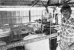
Plant designer Floyd Butterfield
After reviewing 17 submitted designs and closely monitoring the performance of three finalists, an 11 member judging panel representing government, universities, agricultural organizations and the ethanol industry, selected the Gildred/Butterfield ethanol fuel plant in Paso Robles as the winning design. The report that follows, authored by Floyd Butterfield, the designer and operator of the Gildred/Butterfield plant, documents the plant's design, construction, operation and performance.
The Gildred/Butterfield ethanol fuel plant design is offered as one workable approach to ethanol fuel production. Though the design is adaptable to a variety of feedstocks and operating conditions, it may not be the most suitable design for every situation. Careful consideration of site specific factors including feedstock costs and availability, capital requirements, labor inputs, energy inputs and ethanol and co-product markets is critical in determining the technical and economic feasibility of any ethanol production project.
Other viable advanced ethanol production technologies including continuous cooking and fermentation and vapor compression distillation are not part of the Gildred/Butterfield plant and consequently are not detailed in this report. These and other advanced technologies may be considered in conjunction with the Gildred/Butterfield design. Mr. Butterfield has added to the report his recommendations on potential improvements and variations on his as-built design. A number of these recommended refinements are now being incorporated into the Gildred/Butterfield plant as it undergoes continuous development.
Special attention is called to the Notice and Disclaimer appearing on the inside of the front cover of this report. This material should be read carefully by all persons considering construction and operation of an ethanol fuel plant.
For more information on ethanol production contact:
State of California
Department of Food and Agriculture
Long Range Planning Unit
1220 N Street, Room 104
Sacramento, California 95814Table of Contents
Acknowledgements
Preface
Introduction
Plant Description
Front-End Handling Equipment
Cooker
External Heat Exchanger
Solid-Liquid Separators
Mash Storage
Fermentation Section
Distillation Section
Boiler
Stillage Recovery
Warm Water Storage
Electrical System
Plant Operating Manual
Feedstock Evaluation
Front-End Handling
Cooking
Solid-Liquid Separating
Mash Storage
Fermenting
Distillation
Boiler
Plant Performance Data
Production Capacity
Energy Efficiency
Table 1, Cooker Energy Requirements
Table 2, Distillation Energy Requirements
Table 3. Plant Electricity Use
Plant Construction Guide
Front-End Handling Equipment
Cooker
External Heat Exchanger
Solid-Liquid Separators
Mash Storage
Fermentation Section
Distillation Section
Boiler
Stillage Recovery
Warm Water Storage
Recommendations
Appendixes
Appendix A - Lists of Equipment
- List of Equipment, Plates 1 and 2
- List of Equipment, Plate 3
- List of Equipment, Plate 4
- List of Equipment, Plate 6
Appendix B - Plant Equipment Cost
Appendix C - Plant Operating Costs
Plates - the blueprints
Plate 1, Ethanol Plant (plan view)
Plate 2, Ethanol Plant (elevations)
Plate 3, Cooker
Plate 4., Screw Press
Plate 5, Screw Press Details
Plate 6, Distillation Columns
Plate 7, Plate Details
Plate 8, Flow Diagram
Introduction
This report provides detailed information concerning the design, construction, operation and performance of the Gildred/Butterfield Fuel Alcohol Plant. In January, 1982 this plant was awarded first place in the California Alcohol Fuel Plant Design Competition. The competition was sponsored jointly by the California Department of Food and Agriculture and the State Solid Waste Management Board.
The Gildred/Butterfield Fuel Alcohol Plant is located on a ranch approximately six miles north of Paso Robles, California. It presently is in operation on a daily basis.
The plant currently processes off-market barley, wheat and screenings, although it is adaptable to a wide range of feedstocks.
For additional information on this plant contact Floyd Butterfield at 805-467-3417.Plant Description
Front-End Handling Equipment
Front-end handling involves receiving and storing the feedstock and preparing it for processing. The equipment in this portion of the plant may vary substantially for different feedstocks. The plant designer/builder should specify and select equipment suitable for the proposed feedstock.
Grain may be received and stored in any of the commonly accepted ways. The first important step in processing for alcohol recovery is the reduction of the feedstock particle size. Size reduction will render the feedstock more susceptible to rapid enzyme breakdown and efficient mixing. In selecting a specific grinding technique, one must also consider the solid-liquid separating method used later in the process and the end-use of the processed feedstock.
There are two basic types of mills for grinding grains -- the roller mill and the hammer mill. The roller mill is suitable for low-moisture grains that crack easily. On such feedstocks, the roller mill produces uniformly reduced grain with a low percentage of fines. A hammer mill can successfully grind a wider variety of feedstocks.
Feedstocks should be ground with either type of mill to the point where finer grinding provides no further increase in alcohol yield or makes processed feedstock recovery uneconomic.
If the feedstock contains foreign material (such as dirt clods, rocks, trash, etc.) it should be cleaned before being sent to the mill. Any mill should also be protected by a magnetic trap.
For the plant shown on Plate l, feedstock receiving, storage and milling is done at another location. Trucks unload over a bottom-dump hopper and grain is augered into a 100-ton storage bin. As needed, the grain is milled by a 5HP roller mill, which is fed from storage by an auger via a scalper and magnetic trap. The ground grain is augered into a truck and transported to the plant.
Following particle-size reduction, the feedstock is augered into the feedstock storage tank shown on Plate 1 (No. 28). From there it is augered into the scale hopper, weighed and then augered into the cook tank. The scale hopper shown on Plate 1 has only a 500 lb. capacity so it must be loaded several times for a typical 3000 lb. batch.
A more efficient design would be to have the feedstock storage tank or cooker on a scale itself.Cooker
Cooking involves the breakdown of the starch contained within the feedstock to sugar. This breakdown is accomplished by mixing the feedstock with warm water and enzymes and then injecting steam to further heat the mixture.
The batch cooker shown on Plate 1 (No. 20) is a 3000 gallon mild steel tank. It is insulated with a minimum of two inches of urethane foam. The tank is positioned on two steel support pillars and tilted toward the outlet at an approximately 10 degree angle (Plate 3).
The cooker is equipped internally with a 1-1/4-inch diameter, perforated steam line for direct injection of steam. The steam line runs the length of the tank and is positioned slightly off-bottom as shown. It has 1/8-inch diameter holes spaced 2.5 inches apart along its entire length. The steam line from the boiler to the cooker is 1-1/4-inch diameter and fitted with a globe valve for steam flow regulation and a check valve to prevent backflow to the boiler. A back-pressure regulator may also be required in this steam line depending on the other steam demands placed on the boiler during cooking.
The cooker also contains a paddle-type mixer as shown in detail on Plate 3. The mixer shaft is coupled by a chain drive to a motor/gear reducer combination on top of the cooker.
Inlets and outlets to the cooker are via 2-inch diameter, full opening ball valves and hose connections.External Heat Exchanger
The external heat exchanger (No. 19, Plate 1) is used to cool the contents of the cooker and to cool fermenters when necessary. It consists of a 2-inch diameter copper pipe within a 2-1/2-inch diameter copper pipe. The material to be cooled is pumped through the inside pipe while water flows through the annulus around the inside pipe and in the opposite direction. The smaller tube has baffles welded on its outside each 3 feet along its length to support it inside the larger tube and to create turbulent water flow.
This exchanger should be a minimum of 20 feet long. (An alternative to this external heat exchanger would be to install copper coils inside the cooker and pump cooling water through them. That method has the advantage of lower pumping cost but makes cooker cleanout more difficult.)
Connections to this heat exchanger are made via 2-inch hose connections.Solid-Liquid Separators
In the cooker, the starch contained within the feedstock is converted to soluble sugar. At this stage, the entire mash could be fermented. An alternative is to first separate the solids from the liquids after the starch has been converted to soluble sugar and then ferment the liquids only. The plant designer and/or operator must make this decision based on feedstock type and cost, by-product value, need for fermenter agitation, separation efficiency, etc. In any case, the solids and liquids are usually separated at some stage in the process.
The plant shown on Plate 1 uses a two-stage separation process. First, the mash is pumped from the cooker to a Sweco separator (No. 13, Plates 1 and 2). This separator is a vibrating screen type. Liquids that contain fermentable sugar pass through the screen and discharge to one of the fermenters via a two-inch hose. The solids move off the screen and fall into the hopper of the screw press (No. 12, Plates 1 and 2).
The screw press is shovn in detail on Plates 4 and 5. As the mash is augered through the press tube, the excess liquids that fall through the perforations are collected in the catch basin and pumped back onto the Sweco. The solids continue along the tube, are pressed in a short, augerless section at the end of the tube and then fall by gravity into the mash storage bin (No. 14, Plates 1 and 2).Mash Storage
The pressed mash, at about 65% moisture, can be stored until enough is accumulated for transport or direct use.
The mash is stored in a fully enclosed wooden box (No. 14, Plates 1 and 2). This box has a metal frame that is faced on the inside with 3/4- inch-thick plywood. The plywood should be treated with a moisture sealant.
Mash falls into the box by gravity through a small door at the top. The bin can be emptied by opening the full-width doors on front and using a front-end loader.
Carbon dioxide from the fermenters is piped to the mash storage bin. This keeps the mash fresh (for up to one month) until it can be used.Fermentation Section
Each fermenter (No. 8, Plates 1 and 2) consists of a 1700-gallon plastic tank. Each tank is positioned on a stand consisting of a two-inch box steel floor frame with two-inch diameter steel pipe legs. The stand tilts the fermenter toward the outlet at an approximately 7 degree angle. Each fermenter is equipped with a thermometer and a second, off-bottom outlet for drawing samples and mixing the fermenter contents with a pump. It may be desireable to equip each fermenter with a built-in mechanical agitator to help speed the fermentation and aid in complete tank drainage.
Discharge from each fermenter is through a two-inch diameter hose via a two-inch, full-opening ball valve.Distillation Section
The distillation section of the plant is shown on Plates 1 and 2 and in detail on Plate 6. The distillation column internals are shown on Plate 7.
Following fermentation, each fermenter's contents are pumped to the beer well (No. 2, Plates 1 and 2). The beer well is a 2300 gallon plastic tank on a stand. During distillation, the beer is pumped continuously from the well by the beer feed pump (No. 10, Plate 1) to the tube-side of the condenser/preheater (No. 7, Plate 6). This is a 4-pass, tube-in-shell heat exchanger as specified in Appendix A. The beer then flows to the tube-side inlet of the second beer preheater (No. 1, Plate 6). From the outlet of this preheater, the beer is fed into the downcomer of the second highest plate in the stripping column.
In the stripping column, the feed falls down the downcomer and impinges on the blank portion of the plate below (see illustration of sieve plates, Plate 7). It then travels across the perforated portion of that plate, over the outlet weir, and down the downcomer. After traveling down the entire length of the column and across each sieve plate, the resulting stillage is pumped through the shell side of the second stage beer preheater (No. 1, Plate 6) and to the stillage holding tank (No. 7, Plates 1 and 2).
The purpose of the stripping column is to remove the alcohol from the beer feed stream. Steam is injected into the base of the stripping column. The rate of steam addition can be controlled by a pressure reducing valve.
More accurate steam flow control can be obtained through the use of a temperature-controlled steam valve. The steam rises through the plate perforations and carries with it the alcohol in the feed and some water vapor.
The vapors from the top of the stripping column proceed through the two-inch diameter exhaust tubing shown on Plate 6 and enter the base of the rectifying column. These vapors then rise through the perforations in the plates of this column and exit at the top, into the shell side of the condenser/preheater (No. 7, Plate 6). Since the condenser/preheater is only a partial condenser, the ethanol proceeds next to the air-cooled heat exchanger (No. 8, Plate 6). This exchanger completely condenses and may sub-cool the product slightly. The alcohol then flows by gravity through a single-pass, water-cooled, tube-in-shell heat exchanger (No. 10, Plate 6). By controlling the rate of water flow through this exchanger, the temperature of the alcohol entering the reflux drum can be maintained at a constant. These multiple condensers/subcoolers allow maximum beer preheat and minimize the use of cooling water.
The reflux flow rate is controlled by a temperature-regulated valve whose sensor is placed in the vapor space at the top of the rectifying column (operating experience indicates that a more appropriate sensor position is approximately two-thirds of the way down the rectifying column). The reflux controller shown on Plate 6 (No. 12) contains a flowmeter to monitor the reflux flow.
Ethanol that is not returned to the rectifying column as reflux flows out the overflow of the reflux drum and to the plastic, final product holding tank.Boiler
Heat in the form of steam is supplied to the cooker and distillation section by a 10 horsepower, propane-fired boiler (No. 17, Plate 1). This is a fully packaged unit which contains all combustion controls and feedwater reservoir, pump and controls.
Feedwater to the boiler must first pass through a water softener (No. 6, Plate 1) and should be preheated as much as possible. Feedwater preheat can be obtained from the stillage stream during distillation, from boiler exhaust gas, from water discharged from heat exchanger No. 10, Plate 6, or from the external heat exchanger.Stillage Recovery
The stillage from the stripping column consists of hot water containing dissolved and suspended feedstock solids not removed by the separators and dead yeast cells. The stillage is pumped from the stripping column to the stillage holding tank (No. 7, Plate 1).
Approximately 25% to 40% of the hot stillage can be reused in the next cook batch. This accomplishes a substantial savings in process water and energy consumption since each cook begins with preheated water. As the amount of stillage that is recycled in subsequent batches increases, mixer motor load increases and solid-liquid separation become more difficult. Very high rates of recycling (i.e. greater than about 40%) may impair fermentation.
The stillage that is not recycled can be sold as a liquid feed or fertilizer or discharged to an outside holding pond. If treated as a waste, local regulations must be followed as the stillage is usually high in B.O.D. and total solids, and can create an odor problem if not disposed of properly.Warm Water Storage
This system consists of a 2300-gallon plastic water storage tank, pump and pneumatic tank as shown on Plate 1 (Nos. 3, 4, & 5). Warm water from the outlet of the water-cooled heat exchanger in the distillation section (No. 10, Plate 6) and from the external heat exchanger (No. 19, Plate 1) is piped into the water holding tank. This water may then be used in the next cook batch, as plant washdown water, or directed to the softener and used as boiler feedwater.
Electrical System
The method of wiring the plant will depend on its location (indoors or out), layout and size. In general, an electrical contractor should be contacted to do this work as it should all meet the National Electrical Code and any other applicable local codes.
Excluding front-end equipment, plant electrical demand can be met by a 20 kVA transformer. A roller or hammer mill may significantly increase this requirement as will a feedstock storage and handling system. Three phase service of at least 220 volts is recommended for motors above 1-2 horsepower to increase motor reliability and useful life.Plant Operating Manual
Feedstock Evaluation
Before purchasing or processing a feedstock its potential alcohol yield should be established. If the feedstock is a well-known commodity, its potential alcohol yield can probably be obtained from books or other literature. If not, a sample should be sent to a laboratory for starch and/or sugar analysis.
It should be remembered that the values obtained from lab analysis may not be directly indicative of the practical yield obtainable. The lab procedure may vary in method as well as in scale from plant procedures and the starch or sugar identified may not be fermentable.
Feedstock evaluation should provide the plant operator with an idea of the potential alcohol yield and practical alcohol yield obtainable.Front-End Handling
There are at least three main tasks to accomplish with front-end equipment. These are:
- Receive and store the feedstock so that its quality does not diminish.
- Clean the feedstock to protect processing equipment and insure feedstock quality.
- Reduce the feedstock particle size so that the starch or sugar can be recovered most economically.
The types of equipment used to accomplish these tasks may vary depending on feedstock type. In any case, the equipment must all be well-maintained and its performance monitored or periodically tested.
The weight of the cleanings or rejected material should be recorded so that the plant operator is aware of what percentage of received material is actually used as feedstock.
Milling is one of the very important steps in processing. Before processing large amounts of any one feedstock, some initial batches should be run to determine that particle size which results in optimum process efficiency. A finer grind aids in alcohol recovery but may hinder recovery of the processed feedstock. Once the optimum size is known, and the mill is adjusted to deliver that size, frequent monitoring of mill performance is necessary. A sieve analysis is most often employed to monitor the grind.
Before the feedstock is further processed, it should be weighed. Any suitable and reliable weighing equipment can be used. This final weighing is the first step in batch processing. The origin of the feedstock should be recorded on a suitable form along with the measured weight and date of processing.Cooking
Starch feedstocks must undergo a process that breaks the starch down into fermentable sugars. The sugars can then be utilized by yeast to produce alcohol and carbon dioxide.
The plant shown on Plate 1 is designed to use enzymes to accomplish starch breakdown. When employing enzymes, there are actually two steps to the breakdown process. The first step is to heat the water/feedstock mixture in the presence of an enzyme. This step, called cooking or liquefaction, breaks the individual starch molecules out of the tight feedstock matrix. Also, these starch molecules are partially hydrolyzed or slightly reduced in size to 'dextrins'. The second step in the enzymatic process, termed 'saccharification' is to convert the dextrins to the fermentable sugar glucose. This is accomplished with the aid of a second enzyme which is added to the mash after cooling it from cooking temperatures. The enzyme used for liquefaction is called an alpha amylase while that used for saccharification is termed amyloglucosidase. These two enzyme varieties are available from many manufacturers.
Each of these manufacturers can provide specific information regarding the recommended use of their product. In practice, these recommended procedures should be tested and modified to provide optimum results with that feedstock being processed.
A recommended cooking procedure for wheat screenings, employing the cooking equipment described in the Plant Description section, is as follows:
- Approximately 600 gallons of hot water and/or stillage at 170 degrees F is added to the cooker. To prevent mixer motor overload and separating and fermentation problems, not more than 300 gallons of stillage should be used without previous testing. For most grains, the amount of liquid used at this time is about 20 gallons per hundred weight of grain to be cooked.
- The mixer is started and the pH adjusted to 6.0-6.5 with lime. Approximately 1.8 pounds of Miles Laboratories' alpha amylase, called Takatherm, is added. The amount of Takatherm added at this time is about 0.06% of the dry weight of grain to be used.
- 3000 pounds of ground wheat screenings are added to the cooker at a rate that will allow efficient slurrying. Steam is admitted to the cooker to maintain the 170 degree F temperature.
- The rate of steam addition to the cooker is increased to the point where faster heating prevents efficient agitation. The mash is heated to 210 degrees F and held at that temperature until complete or near-complete liquefaction. The hold temperature and time depend on feedstock type; for example, barley can be liquefied more easily than corn or wheat.
- The mash is rapidly cooled, first by the addition of sufficient cool water so that the brix reading is in the 16-20 range.
- Once the mash is below 190 degrees F, an additional 0.9 pounds of alpha amylase is added (approximately 0.03% of the dry grain weight).
- The mash is further cooled to a maximum temperature of 140 degrees F, by pumping it through the external tube-in-tube heat exchanger.
- The pH is adjusted to 4.0-4.4 with dilute hydrochloric acid.
- Approximately 2 pounds of Miles Laboratories amyloglucosidase, Diazyme, is added to the cooker (approximately 0.07% of the dry grain weight). The mash is held at not more than 140 degrees F for one to two hours and then separated.
Solid-Liquid Separating
Solid-liquid separation involves recovery of that portion of the feedstock which cannot be reduced to a fermentable form by the cooking and conversion processes..
Separation may take place either before or after fermentation -- this choice must be made by the individual plant operator. (It could even occur after distillation, however this is difficult for continuous distillation where low flow rates are involved.) Separation before fermentation alleviates the problems associated with handling a heavy slurry (mainly mixing and additional cooling). However, separation after fermentation may result in the recovery of additional alcohol from the feedstock.
To separate, the mash is first pumped to the Sweco (No. 13, Plates 1 and 2) using the variable speed, air-diaphragm pump shown on Plate 1 (No. 16). The pumping rate can be controlled at the Sweco by varying the amount of air reaching the pump via an overhead airline.
The Sweco can separate a grain mash at about 600-900 gallons per hour when using the 64 TBC screen as specified in Appendix A. The liquids flow by gravity, via a two-inch hose, to either a fermenter or the beer well, depending on where in the process separation is accomplished.
Solids discharge from on top of the Sweco's screen into the inlet hopper of the screw press. The press, No 12, Plates 1 and 2, continuously squeezes excess liquids from the mash solids and discharges the solids into the mash storage bin. The liquids from the press are caught in its catch basin and pumped back on to the Sweco screen.
Press performance and capacity are affected by many variables. Feedstock type, cooking procedure, solids feed rate, auger speed, blank tube length and discharge door pressure all affect press operation. In general, the maximum discharge capacity of the press is about 3000 pounds per hour of approximately 65% moisture product when it is being fed by the Sweco. Feeding whole mash directly to the press significantly reduces its discharge capacity. The press shown and described on Plates 4 and 5 is adjusted for wheat feedstocks. The effects of the various factors controlling press performance can be described as follows:
Factors Controlling Press Performance
1. Feedstock
Due to their chemical composition,some feedstocks naturally press drier than others. High protein ( in grains) and pectin (in fruits) make feedstocks containing these slippery and difficult to press. Pretreatment with enzymes (protease or pectinase) can break down these substances and greatly improve press performance.
2. Cooking
Incomplete starch conversion can make the feedstock slippery and difficult to press. Complete starch breakdown is necessary for efficient press operation.
3. Solids Feed Rate
Feeding solids to the press too rapidly will result in either a choked inlet hopper and eventual overflow or motor overload. Alternatively, it will require reduced discharge door pressure resulting in greater throughput but yielding a higher moisture product.
4. Auger Speed
A faster auger speed will result in greater press capacity. It will also necessitate the use of more power to exert the same pressure without motor overload.
.5. Blank Tube Length
The length of the blank auger tube section, at the end of the screw, plays a critical role in efficient press operation. A longer blank section increases the pressure at the end of the screw, usually resulting in a drier product. However, increased pressure requires more horsepower and reduces throughput. A shorter section is required for materials that press very dry.
6. Discharge Door Pressure
The pressure exerted on the press cake by the discharge door will also vary the cake dryness and press capacity. The press should be adjusted so that the blank tube length alone provides most of the back pressure while the door acts as a fine adjustment.Mash Storage
The mash.storage bin is filled by the gravity discharge of pressed feedstock through a hinged door in the top of the bin. Except when separating, this door remains closed.
When the mash is to be shipped or used, it can be removed from the bin by opening the full-width doors on the front of the box and using a front-end loader.
Periodically, the box should be rinsed clean with water and then sprayed with a dilute mixture of bleach and water.
This will prevent a buildup of harmful micro-organisms in the mash storage bin.Fermenting
The fermenters may be filled either with the liquid discharged from the Sweco or with the whole mash (probably requiring installation of fermenter mixers). In either case, the volume of liquid sent to the fermenter should be recorded, along with the brix reading, pH and temperature.
In general, the brix reading should be approximately 16-20. Variations from these figures will necessitate adjustment in the amounts of water added to the batch during cooking. The pH should be approximately 4.0-4.5 and the temperature 80-95 degrees F.
The next important step is to add distillers' yeast to the batch. There are many yeast manufacturers and each will provide instructions on the use of their yeast and the desired fermenter conditions (brix, pH and temperature) upon yeast addition. To promote rapid fermentation, the yeast should first be added to a starter tank. This tank should contain a small portion of the fermentable liquid mixed with water and adjusted to optimum fermenter conditions. The yeast should be allowed to propagate in the starter tank for 15-30 minutes before being sent to the fermenter.
As fermentation commences, the yeast will consume the fermentable sugars and yield mainly ethanol, carbon dioxide gas and heat. Ethanol will remain in solution while carbon dioxide gas will rise through the liquid and fill the head space in the fermenter. The carbon dioxide can be piped out of the top of the fermenter and allowed to flow to the mash storage bin. If the heat released by the reaction causes the fermenter temperature to rise to 95-100 degrees F it must be removed or the yeast could die. This can be done using the external tube-in-tube heat exchanger via a pump and hose connections. The need for fermenter cooling will depend on batch size, feedstock type and outside air temperature.
The pH should be monitored throughout fermentation and a value much below 3.5 usually indicates that some bacterial contamination has occurred. The existence of organisms other than yeast in the fermenters generally will cause a decrease in ethanol yield. Better fermenter cleaning prior to filling is required and additional care must be taken so that the mash is not exposed to competing microorganisms prior to fermentation.
Fermentation is complete when there is no further evolution of carbon dioxide gas. This usually requires 48-72 hours. The tank contents are either pumped to the beer well or to the Sweco (for fermentation with solids).
The fermenter should be emptied completely, rinsed with water and then cleaned with a bleach solution or steam.Distillation
The distillation unit shown on Plate 6 is designed for continuous operation. There are many variables affecting system performance, each of which must be understood and controlled within certain limits for satisfactory operation.
These variables are as follows:
Factors Affecting Distillation System Performance
1. Operating Pressure
The pressure at which the columns operate affects the system in two ways. First, the relationship between the boiling points of ethanol and water varies with pressure. And second, the pumps in the distillation section are selected based on a certain operating pressure. The distillation unit shown on Plate 6 is designed to operate at atmospheric pressure by venting through the reflux drum.
2. Beer Feed
The beer feed can vary in its alcohol content, temperature and rate at which it is pumped to the columns. All three of these variables affect steam useage. The beer feed rate and the quantity of alcohol in the beer determine the alcohol output from the columns. For economical operation, the beer feed should contain a minimum of about 7% alcohol by weight. The columns shown on Plate 6 are designed to handle a beer flow rate of between 90 and 140 gallons per hour.
3. Reflux Flow
The rate at which alcohol is refluxed back to the top of the rectifying column affects the proof of the final product and system heat consumption. A high reflux flow results in higher proof alcohol but also significantly increases heat demand. The reflux flow should be maintained at the minimum rate which provides desired product quality.
4. Heat Rate
The amount of heat supplied to the base of the stripping column is primarily determined by reflux flow and the inlet beer feed temperature and rate. Insufficient heating will result in alcohol being lost out the column bottom. Too much heating requires the use of additional boiler fuel and condenser cooling and may unnecessarily raise operating costs. The heating rate should be adjusted so that the temperature at the base of the stripping column is maintained at about the boiling point of water for the particular absolute system operating pressure.
5. Condenser Heat Rejection
Heat must be removed f rom the alcohol vapors by the condenser system. If the condenser does not remove enough heat, then alcohol vapor will be lost out the vent and/or no amount of reflux will be sufficient to cool the rectifying column and obtain high-proof product. Excessive heat rejection allows the use of too much cooling water which may unneccessarily raise operating costs.
Start-up and operation of the distillation system shown on Plate 6 is as follows:
- Check to be sure instrument air is being properly supplied to all pneumatic controls (Nos. 4 and 12).
- Slowly admit steam to the base of the stripping column.
- When the steam has reached the base of the rectifying column, turn on beer feed pump (No. 10, Plate 1) and slowly initiate beer flow.
- Turn on pumps (No. 6) at the bases of both distillation columns; turn on condenser/subcooler fan (No. 9) and subcooler (No. 10) cooling water. When vapor reaches the top of the rectifying column, turn on reflux pump and set reflux controller (No. 12) to initiate automatic temperature control.
- Adjust cooling water flow to maintain desired reflux drum temperature.
- Adjust beer feed rate to final, desired value.
- Adjust steam rate to maintain proper operating temperature at the base of the stripping column.
- Measure final product proof after system has stabilized and adjust reflux controller and steam flow to provide desired proof with minimum energy consumption.
After start-up, the system will stabilize and remain so as long as there are no variations in external inputs (i.e. changes in steam temperature, pressure or flow rate, cooling water temperature or flow rate or beer feed enthalpy).
Periodic observation and adjustment or additional automatic controls are needed to insure continuous product quality.Boiler
Efficient boiler operation is very important since it provides most of the process energy to the plant. The boiler should be installed, operated and maintained according to the manufacturer's directions. In addition, boiler efficiency should be regularly tested. Inefficiency can usually be attributed to improper feedwater treatment and subsequent fouling problems, lack of feedwater pre-heating, or improper burner adjustment. Any of these problems should be corrected as soon as possible.
The two heat loads placed on the boiler, distillation and cooking, both require only low-pressure steam. The operating steam pressure should be selected based on the magnitude of these two loads and the steam piping distances required in the plant. Local, state and federal regulations may also affect the selection of a certain operating pressure. The boiler shown on Plate 1 operates at 30 psig.Plant Performance Data
Production Capacity
The distillation portion of the plant shown on Plates 1 and 2 is designed to operate continuously, 24 hours per day. Nominal production capacity is 10 gallons per hour of 190 proof ethanol. Based on operating six days per week, annual ethanol production is 70,000 to 75,000 gallons.
In addition to ethanol, the plant produces one or more saleable coproducts, depending on the base feedstock type.
Using grain feedstocks, continuous operation would require about three tons per day. Processing would yield the ethanol as well as approximately three tons per day of a high-protein, high-moisture feed supplement. Approximately 2500 gallons of stillage would also be produced on a daily basis, at least 25% of which could be recycled into following cook batches and the remainder sold as a liquid feed supplement or fertiizer.Energy Efficiency
Most of the process energy consumption is due to steam useage in the cooking and distillation sections of the plant.
The amount of steam used in cooking can vary widely depending on the feedstock type and plant operating schedule. Sugar-based feedstocks may not require any cooking while some starch feedstocks (wheat and corn for example) require high cooking temperatures and long hold times. When the plant is operating continuously, there is recycleable hot water and stillage available whereas if it is operated only intermittently this may not be the case.
Typical cooker steam useage is illustrated in Table 1.
Steam useage in distillation can vary widely depending on the operating reflux ratio, percent alcohol in the beer and amount of beer preheat. Typical steam requirements for distillation are illustrated by Table 2. The example shown is for distillation of a typical 3000 lb batch of wheat screenings yielding approximately 1200 gallons of 10% by volume ethanol beer. This could be pumped to the stripping column at 120 gallons per hour. In passing through the two stages of beer preheat, it would be heated to approximately 180 degrees F before entering the stripping column. The ethanol would be vaporized at the top of the rectifying column at about 173 degrees F. A reflux ratio of approximately 3 to 1 (reflux 36 gallons per hour for a product rate of 12 gallons per hour) would be required to obtain 190 proof product. The stillage would pass out the base of the stripping column at about 212 degrees F.
Tables 1 and 2 show that efficient values for total steam energy consumption, when processing a grain-type feedstock, is 20,877 BTU's per gallon ethanol (2,441 BTU/gallon for cooking and 18,436 BTU/gallon for distillation). This excellent efficiency is obtained only with recycling of hot liquids, good boiler system maintenance and complete insulation. Appendix C presents a more thorough discussion of plant energy use and illustrates the sensitivity of the energy use figure to operating procedures.
Table 1
Cooker Energy Requirements
(See discussion in Appendix C.)
where:
BTU's to cook = BTU's to heat liquid + BTU's to heat feedstock + BTU's lost Boiler system efficiency
BTU's to heat liquid = (wt. of liquid) (spec. heat of liquid) (final cook temp. - initial cook temp.)
BTU's to heat feedstock = (wt. of feedstock) (spec. heat of feedstock) (final cook temp. - initial cook temp)
BTU's lost = 5% of BTU's to heat liquid + feedstock for insulated cookerFor example, when processing wheat screenings on a continuous basis, a typical cook proceeds as described in Plant Operating Manual, Cooking. Energy consumption in that case is:
BTU's to cook = 1. 05 ((600 gal) (8.3 1b/gal) (1.0 BTU/lb F) + (3000 lb) (0. 2 BTU/lb F)) (210 F-170 F) 0.80 292,950 BTU's to cook 3000 lbs. grain