By S. Friedman,* A.S. Mehta** and P.L. Thigpen***
From Considine, Douglas M. (Ed-in-Ch): Energy Technology Handbook (McGraw-Hill, 1977)
Scanned by F. Marc de Piolenc
piolenc@mozcom.com
*Assistant Research Supervisor and Supervisory Chemical Engineer, Pittsburgh Energy Research Centre of the U.S. Bureau of Mines
**Formerly Staff Engineer, Chemical Process group, The Rust Engineering Company (a subsidiary of Wheelabrator-Frye Inc.), Birmingham, Alabama
***Principal Process Engineer, Chemical Process Group, The Rust Engineering Company (a subsidiary of Wheelabrator-Frye Inc.), Birmingham, Alabama
IN a continuing search for alternative supplementary energy sources, scientists at the Pittsburgh Energy Research Center of the Bureau of Mines, U.S. Department of the Interior, have successfully converted wood wastes, bovine manure, and municipal organic refuse into oil in the laboratory. Actually, any cellulosic material can be converted to oil by this process. This is an important technological development in view of the energy shortage as well as the waste-disposal problems. It must he noted that as of late-1974 only bench-scale work had been carried out.
With the technical feasibility demonstrated in the laboratory, a preliminary economic feasibility study was made by an engineering firm for the Bureau of Mines. The results of the study were encouraging, and, as a result, a pilot plant is being constructed at the Albany Metallurgical Research Center of the Bureau of Mines in Albany, Oregon. The Rust Engineering Company was awarded a contract to design this pilot plant, which will further define the process and reveal any operational problems that may occur upon scale-up so that remedial technology can be developed for the design of large plants. Wood chips were selected as feedstock for this pilot plant.
Economics
The total of various solid organic wastes generated yearly in the United States is about 3 billion tons (Ref. 1). The population is rising, and so is the amount of solid wastes per person. Two billion tons of waste per year, containing approximately 50 percent organic matter, could yield some two billion barrels of oil annually. This is approximately 50 percent of the 1970 United States demand for oil (Ref. 2). In essence, this is a means of utilizing solar energy which is, of course, the basis of cellulose production. Looking into the future, it is possible to cultivate fast-growing crops on a large scale to serve as feedstock for such an oil-producing plant. No economics are available at the present time for such a large-scale, integrated agricultural and oil production facility. The oil produced by this process has a low sulfur content and is suitable for use by power plants or far conversion to gasoline and Diesel fuels. (See also articles on Biochemical Sources of Fuels and Photosynthesis in the Chemical Fuels Technology and the Solar Energy Technology sections of this handbook, respectively.)
According to the preliminary economic feasibility study, a 3000-ton-per-day plant will cost approximately $51.4 million and will have a breakeven operating cost of $7.24 per barrel. It might be pointed out that either a city having a population of 300,000 or a cattle feed lot having 200,000 cattle can feed a plant that would just break even on total costs, including a 20-year amortization of investment (Ref. 1). The foregoing are 1974 dollars.
Process
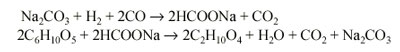
Basically, the process involves reacting carbon monoxide with the wood wastes in the presence of a sodium carbonate solution as a catalyst at up to a temperature of 700 deg F (371 deg C) and up to 4000 psig. Carbon monoxide reacts with sodium carbonate in the presence of water to form sodium formate which, in turn, reacts with cellulose in the wood wastes to form oil and regenerate sodium carbonate. The following reactions are believed to be typical:
The major problem in this process is anticipated to be the introduction of wood wastes into the reactor against a pressure of 4000 psig. An overall process flow diagram is given in Fig. 1.
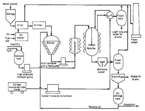
Figure 1
Drying and Grinding
Wood wastes have a high moisture content (up to 50 percent) and practically no ash. For this pilot plant, it was believed necessary to dry the wood wastes to approximately 4 percent moisture content because (1) excessive moisture going into the reactor with the wood effectively reduces the reactor capacity, and (2) dry wood grinds much more easily than wood with a high moisture content. Grinding dry wood to a fine powder is necessary to facilitate pumping a wood-oil slurry. It is anticipated that the process improvement in this pilot plant will allow deletion of the drying step in a commercial plant and also that hardware will be developed to eliminate fine grinding of the wood.
Feed Systems
Because of the difficulties experienced in feeding wood-oil slurry during bench-scale operations, the Bureau of Mines specified that three different feed systems be designed and incorporated for this pilot plant in order to select the best system for commercial use: (1) wood-oil slurry feed, (2) solids feed, and (3) pretreated wood-oil slurry feed. These three feed systems and other process areas are described in the following paragraphs.
Wood-Oil Slurry Feed System
This feed system is shown as part of the overall process illustrated in Fig. 1. The dried and ground wood is continuously mixed with oil to form a slurry with up to 30 percent solids content. For initial start-up, anthracene oil is used; after the plant is in operation, oil produced in the process is recycled for slurry preparation. This slurry is extremely thick and poses a problem in pumping at 4000 psig. A plunger pump with special knife-edged spring-loaded cone valves will be used to develop the required pressure. It is expected that a pump will be developed that will have either mechanically or electrically operated suction and discharge valves to provide positive opening and closing actions and thus minimize plugging problems. A pump of this type already has been built by the Bureau of Mines. Further interest may be generated when this process nears commercialization.
The catalyst used in this process is a 20 percent sodium carbonate solution. A high-pressure plunger pump will be used to develop 4000 psig pressure. Such a pump is not expected to pose any particular problems because the catalyst solution is clear. Although the amount of catalyst is not great, it is anticipated that the aqueous stream recovered from the reaction mixture will be partially recycled in a commercial plant for economy and to minimize waste effluent.
Carbon monoxide will be compressed in a diaphragm compressor to a pressure of 4000 psig and introduced into the reactor through a dip pipe. For this pilot plant, carbon monoxide will be purchased in tube trailers. But in a commercial plant, part of the wood wastes will be used to produce synthesis gas containing hydrogen and carbon monoxide that will be used in the reactor. Synthesis gas is actually better suited for the reaction because its hydrogen content removes sulfur and nitrogen from the wood wastes, forming hydrogen sulfide and ammonia, respectively.
Solids Feed System
The solids feed system is shown in Fig. 2. The direct solids feed system has a major advantage of achieving the greatest throughput for a given size reactor. It also simplifies hardware problems of pumping a slurry. However, the solids feed system is quite complex and expensive.
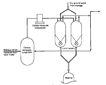
Figure 2
Two methods were considered for feeding solids directly into the reactor: (1) pneumatic, and (2) mechanical feeding. Because of partial pressure considerations in the reactor, carbon monoxide must be used to pneumatically convey and feed the dry solids. Preliminary results of tests conducted in a vendor's laboratory indicated that excessive quantities of carbon monoxide would be required. Because of the gas consumption and the fact that the reactor off-gases will not be recycled or utilized in any manner in this pilot plant, pneumatic feeding was not selected. However, for a commercial plant, where the reactor off-gases could be used for some purpose, as mentioned later, pneumatic feeding would be a possibility.
For this pilot plant, a mechanical feed system incorporating a rotary feeder was designed. The feed system basically consists of two pressure-balanced lock hoppers which will be used alternately. To be able to use conventional rotary feeders, the lock hoppers were designed so that the feeders are installed inside and, therefore, are not exposed to high differential pressure. However, a rotary feeder capable of withstanding a 4000-psig differential is preferred for better access, improved maintenance, and a simpler lock-hopper design. Vendor interest for building such a feeder has been evidenced, but details are not immediately available.
The lock-hopper system will function in the following manner. A lock hopper is filled with wood wastes at atmospheric pressure, pressurized to 4000 psig using carbon monoxide, and the solids are fed to the reactor with the help of the rotary feeder. When the lock hopper is empty, the pressure is reduced, first by venting to a carbon monoxide surge tank, and then to a flare stack. Once the lock hopper is vented to atmospheric pressure, it is ready for the next cycle. The purpose of the carbon monoxide surge tank is to collect most of the carbon monoxide from the lock hoppers, so that it can be recompressed and reused in the next cycle.
Pretreated Wood-Oil Slurry System
The overall pretreatment process is shown in Fig. 3. This is another alternative to feeding wood wastes into the reactor. It is similar to the wood-oil slurry feed system except that it involves pretreatment of wood wastes with water at up to 500 deg F (260 deg C) and up to a pressure of 700 psig. Under these conditions, wood is converted into material similar to charcoal.
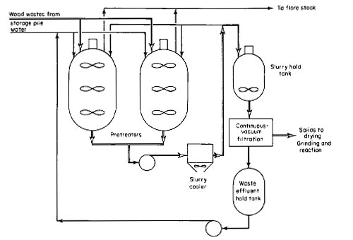
Figure 3
Two pretreaters are provided for this pilot plant for alternate use. A pretreater will be loaded with wood wastes and water and heated up to 500 deg F. This will build up pressure to 700 psig because of the vapor pressure of water. After maintaining the process conditions for the required length of time, the pretreater and its contents, which comprise a 15 percent slurry of pretreated wood in water, are cooled to 150 deg F (66 deg C) through an external pump-around loop, including an air-cooled heat exchanger, and then transferred to a holding tank. The pretreated wood is filtered out, dried, ground, mixed with either anthracene or recycle oil, and fed to the reactor as previously described. The advantage of pretreating the wood wastes is that it can be slurried in oil up to 50 percent.
Reaction
The reaction is carried out continuously in a stirred pressure vessel at 4000 psig and 700 deg F (371 deg C). The process conditions will be optimized in this pilot plant to achieve the lowest operating pressure and temperature. The pressure in the reactor will be controlled by the pressure-reducing valve in the reactor off-gas line. This is an angle valve with Kennametal K-703 trim and seat. This material was selected on the basis of success previously experienced by the Bureau of Mines.
The level in the reactor is maintained by regulating the flow of liquid from the reactor. The level detection in the reactor is a major consideration because of severe process conditions and a 4-l/ 2-inch-thick stainless steel wall for the 24-inch inside-diameter vessel. A nuclear level measurement system was investigated. Because of the geometry of the reactor, the required radiation source level would be high. This could pose a radiation hazard, and, therefore, the method was not selected. Two methods of level detection are designed for the pilot plant: (1) Multiple thermocouples are provided inside the reactor to detect the temperature difference between the gas and liquid phases. This method will function only if there is a measurable temperature difference between the two phases. (2) The second method utilizes a differential-pressure transmitter isolated from the process by a chemical seal. These two methods are provided only to determine their performance.
For control purposes, an overflow loop system, as shown in Fig. 4, is provided down-stream of the bottoms cooler. An enlarged spool piece in the downstream side of the overflow loop seal will maintain a liquid pool. A differential-pressure transmitter will detect the liquid level in this enlarged pool piece. This transmitter is believed to be more reliable because the liquid is cooled down to 400 deg F (204 deg C). The control valve will be similar to the valve used in the reactor off-gas line previously described.
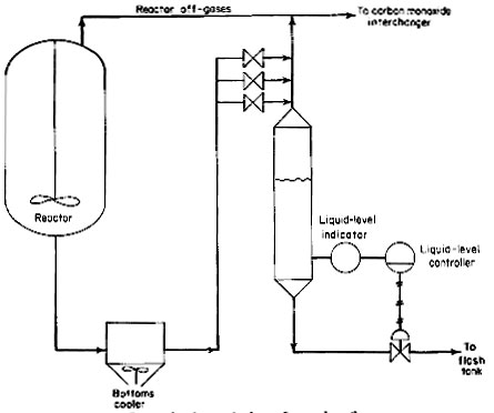
Figure 4
Reactor Off-Gases
After exchanging heat with the incoming carbon monoxide, and after the pressure reduction, the reactor off-gases (consisting primarily of carbon monoxide, carbon dioxide, and water vapor) are cooled and flashed to recover light oils and water. The noncondensible gases are burned in a flare stack. In a commercial plant, it is anticipated that the noncondensible gases will be purified to remove ammonia and hydrogen sulfide and then burned along with a portion of the synthesis gas in a Dowtherm system to provide approximately 90 percent of the heat requirements of the plant. The waste gases will then be vented to the atmosphere.
Oil Recovery
The liquid phase from the reactor is also flashed after it is cooled. Light oils and water are removed from the flashed gases, and the noncondensable gases are disposed of in the same way as the reactor off-gases. The liquid consists mainly of the oil, water, unconverted wood, and sodium salts of organic acids. The liquid phase is centrifuged to remove suspended solids and water. The oil, thus recovered, is recycled back to the processes, as needed, and the remainder is stored as product. The oil produced has the following characteristics:
Specific gravity
1.1
Viscosity, cp (140 deg F, 60 deg C )
515
Heating value, Btu per pound
15,000
Composition, % Carbon
76.62
Hydrogen
7.05
Nitrogen
0.13
Sulfur
0.14
Oxygen
20.05
Environmental Considerations
A flare stack is furnished for this pilot plant to handle unreacted carbon monoxide, hydrogen, and miscellaneous gases. For a commercial plant, a gas-purification system is expected to remove noxious components from the gas stream before discharging to the atmosphere. There will be some liquid and solid wastes. No provisions are made in this pilot plant for their disposal. The quantity and nature of such wastes are not fully known at the present time. It is anticipated that the wastes from this pilot plant will be fully analyzed, and means for their disposal will be developed at a later date.
References
1. Knapp, E.C.: Agriculture Poses Wastes Problems, Environ. Sci. Technol. , vol. 4, pp. 1098-1100, December 1970.
2. Converting Organic Wastes to Oil, U.S. Bur. Mines Rep. Invest. RI-7560, Pittsburgh, Pa., 1971.
3. Friedman, Sam, Henry Ginsberg, Irving Wender, and Paul Yavorsky: Continuous Processing of Urban Refuse to Oil Using Carbon Monoxide, paper presented at Third Mineral Waste Utilization Symposium, IIT Research Institute, Chicago, Mar. 14-16, 1972.
See Liquefaction
Back to Biofuels Library
Biofuels
Biofuels Library
Biofuels supplies and suppliers
Biodiesel
Make your own biodiesel
Mike Pelly's recipe
Two-stage biodiesel process
FOOLPROOF biodiesel process
Biodiesel processors
Biodiesel in Hong Kong
Nitrogen Oxide emissions
Glycerine
Biodiesel resources on the Web
Do diesels have a future?
Vegetable oil yields and characteristics
Washing
Biodiesel and your vehicle
Food or fuel?
Straight vegetable oil as diesel fuel
Ethanol
Ethanol resources on the Web
Is ethanol energy-efficient?